Sysmac Studio TOF Timer: Everything You Should Know

Table of Contents
The TOF Timer is one of the Timer functions found in Sysmac Studio. Timer functions are utilized in automation programming to control time-based operations. There are 5 timers available in Omron Sysmac Studio. In my previous article, I discussed one of these timer functions, the TON Timer. In this article, we will delve into the specifics of the TOF Timer.
What is TOF Timer (Off-Delay)? #
The TOF Timer is commonly referred to as an off-delay timer. The output signal of the TOF Timer is cut after the desired amount of time has passed following the cutting of its input signal. Let’s take an example, suppose we have a light that is controlled by a single toggle button. We wish for the light to turn on immediately upon the button being switched to the ON position, and for the light to turn off 5 seconds after the button is switched to the OFF position.That is where the TOF timer offers its assistance.
Demonstration of TOF Timer in Ladder Diagram and Structured Text Forms #
The TOF Timer can be utilized in two different forms within Sysmac Studio: as a Ladder Diagram and as Structured Text.
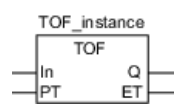
TOF Timer Ladder Diagram #

TOF Timer Structured Text #
TOF_instance (In, PT, Q,ET);
Inputs and Outputs of the TOF Timer #
| Input/Output | Meaning | Description | Valid Range | Unit | |
|---|---|---|---|---|---|
| In | Input | Timer Input | TRUE : Timer Reset Signal FALSE : Timer Start Signal | TRUE or FALSE | — |
| PT | Input | Set Time | Time from when timer starts until Q changes to TRUE | T#0 ms to T#106751d_23h_ 47m_16s_854.775807ms | ms |
| Q | Output | Timer Output | TRUE : Timer output ON FALSE : Timer output OFF | TRUE or FALSE | — |
| ET | Output | Elapsed time | Elapsed time since timer started | T#0 ms to T#106751d_23h_ 47m_16s_854.775807ms | ms |
Utilization of the TOF Timer #
State-1 #
When the In input is activated, the Q output is also activated. Upon deactivating the In input, a wait time of Pt is required for the Q output to become deactivated. Additionally, the state of the timer can be monitored via the Et output.

In the above GIF, a 5-second TOF was utilized. Upon triggering the A contact, the abc output became active. However, upon making the A contact false, the abc output did not immediately transition to false, instead it changed to false after the PT specified time (5 seconds) had passed. During this 5-second interval, even though the A contact was inactive, the abc output continued to remain active. The elapsed time during this interval can be tracked through the def variable.
State-2 #
What if the A contact is triggered again while the Q output is not passive, i.e. after the TOF Timer has started working?

As seen in the above GIF, the A contact is made passive, thereby starting the TOF Timer. If the A contact is triggered again while the TOF Timer is running, it can be seen that the value in the ET output of the TOF Timer is reset and the TOF Timer is restarted.
State-3 #
If the A contact were used in the manner seen in the following GIF, with the rising edge, what would happen?

If the A contact was used as a rising edge, then when it is triggered, the TOF Timer would become active and the abc output would be active for 5 seconds (the value of PT). After the time is up, the TOF Timer would reset and the abc output would become passive. The most important point here is that the TOF Timer becomes independent of the A contact while it is running. This means that there is no way to reset the timer while it is running, whether the A contact is active or passive. The timer will continue to run regardless.
Timing Diagram #
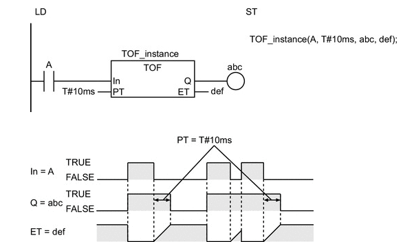
- The TOF instruction outputs FALSE when the set time elapses after the timer starts. The time is set in nanoseconds.
- The timer starts when timer input In changes to FALSE. Elapsed time ET is incremented as time elapses.
- When ET reaches set time PT, timer output Q changes to FALSE. ET is not incremented after that.
- The timer is reset when In changes to TRUE. ET changes to 0, and Q changes to TRUE.
- If In changes to FALSE after the timer is started, the timer is reset even before ET reaches PT.
The following figure shows a programming example and timing chart for a PT of T#10 ms. Variable abc will change to FALSE 10 ms after variable A changes to FALSE.

Things to Pay Attention #
-
The timing error for which Q is TRUE for PT is -100 ns to (100 ns + 1 task period). The above range includes the following:
- The ±100 ns is the timing error of ET.
- Time ET is judged to check if it reaches PT every task period. If time ET reaches PT immediately after the judgment is completed, there is a delay of one task period.
-
The time is displayed in increments of 0.001 ms on the Sysmac Studio, but the timing accuracy is 1 ns.
-
If T#0 ms or a negative number is set for PT, Q will change to FALSE as soon as the value of In changes to FALSE.
-
After this instruction is executed, the value of Q changes to TRUE if the value of In is TRUE. The value of Q changes to FALSE when the set time PT elapses after the timer is started.
-
You can change the value of PT while the value of In is FALSE. Operation is as follows:
| Timer Status | Value of Q | Value of PT after it is changed | Operation |
|---|---|---|---|
| After completion of timing | FALSE | — | The value of Q remains FALSE.The value of ET also does not change. It remains at the same value of PT as before it is changed |
| Timing in progress | TRUE | PT≥ ET | Timing is continued. When the value of ET reaches the value of PT, the value of Q changes to FALSE and ET is no longer incremented. |
| Timing in progress | TRUE | PT< ET | The value of Q changes to FALSE immediately.Incrementing ET stops immediately. |
- If this instruction is in a master control region and the master control region is reset, the timer is reset. The value of ET changes to 0, and the value of Q changes to TRUE.
- If this instruction is used in a ladder diagram, the value of Q changes to FALSE when an error occurs in the previous instruction on the rung.